Containment · Technology Library
GTT NO96: Why Insulation Must Carry Loads as Well as Keep LNG Cold
Two Invar membranes define the NO96 containment principle. Behind them, an evolving insulation assembly must limit heat ingress while providing mechanical support. Understanding both functions is essential to reading the system as an engineer.
Owner-approved educational article · Source review: 16 October 2026 · Research sources reviewed at abstract level where stated · Not an independent class approval or technical certification.
1. The engineering behind the cold cargo
Inside an LNG tank, the metallic surface attracts attention. The less visible structure behind it explains much of how the system works. For an engineer, understanding containment begins with three connected questions: what retains the liquid, what limits heat transfer, and what supports the cargo loads?
GTT describes NO96 as a membrane system with primary and secondary Invar barriers, each 0.7 mm thick. Invar is an iron–nickel alloy containing 36% nickel. The insulation layers support the membranes; the primary membrane contains the cargo and the second provides a further liquid barrier in the event of primary leakage.S1
2. Inside the wall: identify the functions
The following is a conceptual ordering from cargo toward the inner hull. It is a teaching model, not a construction drawing. Corners, penetrations, joints and local support details are omitted.S1S3S4
| Element | Function to understand |
|---|---|
| LNG cargo | Source of hydrostatic loading and, during liquid motion, dynamic loading |
| Primary Invar membrane | Primary liquid boundary |
| Primary insulation assembly | Thermal resistance and membrane support |
| Secondary Invar membrane | Additional liquid boundary |
| Secondary insulation assembly | Further thermal resistance and support |
| Support interfaces and inner hull | Connection to the supporting ship structure |
The term insulation assembly matters. It refers to the engineered combination of materials, geometry and interfaces, rather than assuming that every constituent has the same structural function.
Figure 1 — two engineering views of the same wall
- Solid: conceptual load path
- Dashed: heat transfer
Original MyLNG educational diagram, based on the principles described in S1, S3 and S4. Solid arrows show a conceptual load path; dotted arrows show heat transfer. This functional diagram omits the detailed layer sequence and does not represent a particular variant or approved design.
Text alternative: Cargo loading acts on the membrane and is supported through the containment assembly toward the hull. Heat travels from warmer surroundings through the assembly toward the LNG. The structural and thermal questions concern the same physical system.
3. Why insulation is also a structural system
The thermal task
Insulation reduces the rate at which heat reaches the cargo. Its performance helps determine the vapour quantity that the ship must manage, but heat transfer is not eliminated.S2
Choi and colleagues measured thermal conductivity over a range extending from room to cryogenic temperatures and used those properties in insulation-box calculations. They also examined hull temperature in a scenario involving leakage through the secondary barrier. The abstract connects insulation assessment with the protection of the supporting steel structure, rather than treating evaporation as the only concern.S10
The mechanical task
In the traditional box-based NO96 architecture, the plywood structure has an essential supporting role. The distinction is between the insulating medium and the engineered box assembly: saying that the insulation system carries loads should not imply that loose insulating fill alone forms the structural load path.S1S5
At a conceptual level, pressure acts on the membrane, its backing supports that pressure, and forces pass through the supporting assembly toward the inner hull. The load distribution depends on the geometry and interfaces. The barrier sequence shown above is therefore a physical ordering, not a claim that every force travels through a single identical route.
Two possible structural responses help explain the distinction:
- Buckling: a supporting member loses stability under compression.
- Crushing: material or a component undergoes compressive failure.
Park’s 2019 study addresses crushing of horizontal members in box-type NO96. Its abstract describes small-scale tests and nonlinear finite-element calculations that also account for bending. Park and Lee’s 2018 work addresses buckling. They are separate investigations of different limit states.S5S9
Research by Park and Lee investigates buckling capacity in box-type NO96 containment under sloshing loads, using finite-element calculations with temperature-dependent material considerations. Its abstract explicitly treats dynamic response as part of the strength assessment.S5
Geometry, temperature and loading must be read together
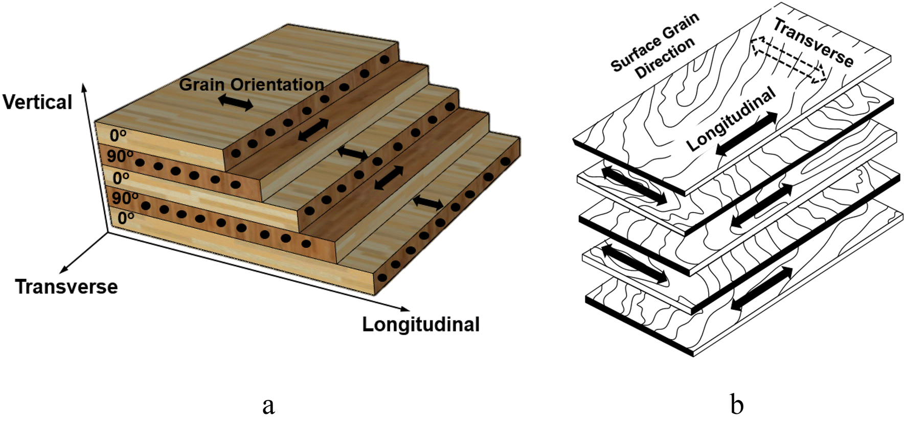
Cha and colleagues tested MUF-resin plywood used in membrane-containment applications. Their experiments varied temperature, specimen thickness and loading direction. They reported changes in mechanical behaviour, including brittle fracture under specified cryogenic test conditions. The work demonstrates why room-temperature strength alone is an incomplete description of a material operating across a thermal gradient.S6
Figure 2 — the material behind the structural question
What this changes in an engineering discussion
| Question | Why it matters |
|---|---|
| Which variant is installed? | The insulation and supporting architecture have evolved. |
| Which component is being assessed? | A material specimen, a box and a complete containment assembly answer different questions. |
| At what temperature and loading direction? | Material behaviour depends on the test conditions. |
| Is the loading static or dynamic? | A short impact requires an appropriate response assessment. |
| What documentation supports acceptance? | General research cannot approve a vessel-specific condition. |
4. Sloshing: from liquid motion to structural response
Sloshing assessment concerns more than describing the movement of liquid. DNV’s historical 2014 methodology overview links load assessment with containment strength and the supporting inner hull, including statistical treatment and model-test scaling. It is useful background, not a current class rulebook.S4
For a box-based NO96 discussion, the Park and Lee study provides a focused example: buckling capacity is assessed against dynamic loading, rather than inferred from a thermal-performance number. Its relevance is the question being investigated: how the supported structure responds to the imposed loading.S5
Service also matters. GTT explains that FSRU/FSU sloshing assessment considers filling levels, site conditions and mooring arrangements when selecting reinforcement. A system intended for one service cannot be assumed suitable for another simply because both carry the NO96 name.S7
5. One membrane principle, several insulation architectures
GTT’s family table distinguishes Perlite, GW, L03 and L03+. The first uses perlite; GW uses glass wool, while the later developments introduce foam into the arrangement. Identify the precise variant before describing its construction.S1
NO96 Super+ retains the double Invar barriers but uses reinforced polyurethane foam panels in both insulation spaces, with glass-wool joints between neighbouring panels. GTT’s development description assigns these panels both insulating and membrane-support functions.S2S3
Manufacturer reference BOR values
BOR means boil-off rate; the values below are expressed as percentage of cargo volume per day.S1S2
| Variant | Construction distinction | Reference BOR (% volume/day) | Reference vessel |
|---|---|---|---|
| NO96 Perlite | Plywood-box arrangement with perlite insulation | 0.15 | 170,000 m³ |
| NO96 GW | Glass wool replaces perlite within the box-based evolution | 0.125 | 170,000 m³ |
| NO96 L03 | Hybrid arrangement incorporating foam into the insulation/support architecture | 0.11 | 170,000 m³ |
| NO96 L03+ | Further development of the hybrid insulation arrangement | 0.10 | 170,000 m³ |
| NO96 Super+ | R-PUF panels in both insulation spaces, with glass-wool panel joints | 0.085 | 174,000 m³ |
Construction descriptions are deliberately at family level. L03 and L03+ require variant-specific drawings to establish the detailed allocation of boxes, panels and interfaces.S1S2S3
The Super+ value is GTT’s stated guarantee for the identified reference design. These are manufacturer figures, with different reference capacities, not comparable measurements from five ships on the same voyage.S1S2
6. BOR is an input to the ship’s energy balance
For a meaningful comparison, ask:
- Are capacity, tank arrangement and reference conditions comparable?
- Is the number a design reference, contractual guarantee or measured result?
- How is gas generation matched to the ship’s consumers and recovery systems?
- What happens when generation and demand differ?
- Are cargo retention, auxiliary energy and emissions evaluated separately?
This is a framework for comparison, not a calculation of voyage savings. A lower published BOR does not by itself establish lower total fuel consumption, lower emissions or better structural reliability.
Related: explore indicative scenarios in the BOG & Propulsion Economics Calculator.
7. Reading NO96 from an operator’s perspective
The following questions connect the design explanation with shipboard awareness. They are an engineering review framework, not operating sequences or alarm settings.
Know the installed configuration
Can the crew identify the containment variant and locate the approved descriptions of its spaces, insulation and support arrangement? Does the training material describe the actual ship, or only a generic NO96 tank?
Read temperature and pressure in context
Which measurements are available, where are they located and what is their intended purpose? Which trends require escalation under the vessel’s procedures? A single reading should not be presented in an educational article as proof of a particular failure mechanism.
Understand barrier-space monitoring
How are the interbarrier and insulation spaces identified on this vessel? Which gas-analysis, pressure and temperature records support an assessment? Public descriptions cannot supply the ship’s nitrogen-control settings or leak-response instructions.
Preserve the condition history
Which inspections, repairs and abnormal observations concern this installation? Are conclusions tied to the actual variant, component and evidence? Generic research should help frame a question, while acceptance and corrective action remain matters for the approved technical process.
8. NO96 and Mark III: compare construction before claims
| Feature | NO96 family | Mark III family |
|---|---|---|
| Primary barrier | Invar | Corrugated stainless steel |
| Secondary barrier | Second Invar membrane | Composite barrier |
| Insulation comparison | Identify the precise NO96 variant | Identify Mark III, Flex or Flex+ |
| Engineering assessment | Examine thermal performance and mechanical support in the actual configuration | Apply the same discipline to the actual configuration |
Construction sources: S1–S3 and S8. The table explains differences; it does not rank operating reliability, maintenance cost or suitability for a particular trade.
Related: read the GTT Mark III, Flex and Flex+ article.
9. How to use the evidence
10. What the system teaches us
For engineers, the enduring questions are concrete: which variant, which component, which loading condition and which supporting evidence? Keeping those questions together is the foundation for an informed technical discussion.
References
Source review: 16 October 2026. Manufacturer descriptions, research findings and MyLNG interpretation are distinguished in the text.
S1 — GTT, NO96 technologies.
Current public product page; membrane data, variant table and reference basis.
Source (opens in a new tab)S2 — GTT, NO96 Super+.
Current public product description; panel arrangement and 174,000 m³ reference guarantee. Manufacturer claims, not independent voyage measurements.
Source (opens in a new tab)S3 — GTT, NO96 Super+ development account.
Panel support and assembly principles. Historical text still contains forecast approval dates; those forecasts are not used as current approval status.
Source (opens in a new tab)S4 — DNV, Revised version of Class Note 30.9 — Sloshing analysis of LNG membrane tanks, 5 September 2014.
Historical methodological context only.
Source (opens in a new tab)S5 — Park, Y. I.; Lee, J. H. (2018), Buckling strength of GTT NO96 LNG Carrier cargo containment system, Ocean Engineering 154, 43–58.
Located and abstract read through Paperguide. Full text unavailable during revision; no numerical findings extracted.
DOI (opens in a new tab)S6 — Cha, S.-J. et al. (2020), Effect of temperature on the mechanical performance of plywood used in membrane-type LNG carrier insulation systems, Journal of Wood Science 66, 28.
Publisher’s full HTML and PDF consulted, including test scope and licensing.
DOI (opens in a new tab)S7 — GTT, FSRU & FSU.
Site-specific service and sloshing considerations.
Source (opens in a new tab)S8 — GTT, Mark III technologies.
Construction comparison only.
Source (opens in a new tab)S9 — Park, Y. I. (2019), Ultimate crushing strength criteria for GTT NO96 LNG carrier cargo containment system under sloshing load, Ocean Engineering 188, 106224.
Abstract and metadata checked through Paperguide; no numerical capacity extracted.
DOI (opens in a new tab)S10 — Choi, S. W.; Roh, J. U.; Kim, M. S.; Lee, W. I. (2012), Analysis of two main LNG CCS (cargo containment system) insulation boxes for leakage safety using experimentally defined thermal properties, Applied Ocean Research 37, 72–89.
Abstract and metadata checked through Paperguide; used only for the stated research scope.
DOI (opens in a new tab)